 |
HomeCore 0.1.3 (07b5544)
Bare-metal personal computer firmware for Cortex-M
|
|
HomeCore 0.1.3 (07b5544)
Bare-metal personal computer firmware for Cortex-M
|
stm32f4discovery target supports ST's STM32F4DISCOVERY board with an STM32F407VGT6. It runs the shell and VFS over a USART2 console (interrupt-driven receive) with a 1 kHz SysTick, clocked from the 16 MHz internal HSI oscillator. The port is cross-compiled in CI and its linked layout has been checked. QEMU has no model for this board, so nothing executes this port automatically. Physical hardware validation is still required.
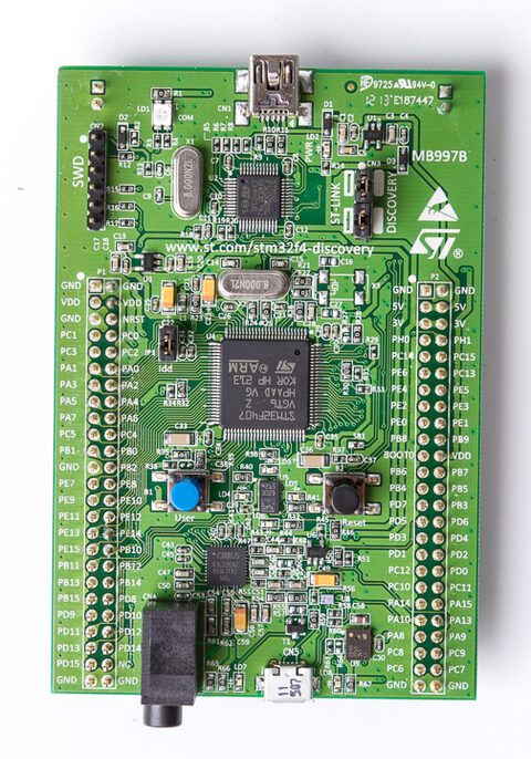
At a glance
| SoC | ST STM32F407VGT6 (st/stm32f407) |
|---|---|
| Core | Cortex-M4F, software floating point |
| Flash | 1 MB at 0x08000000 |
| RAM | 128 KB SRAM at 0x20000000; 64 KB CCM unused |
| Clock | 16 MHz HSI |
| Console | USART2, PA2 TX / PA3 RX, 115200 8N1 |
| Preset | stm32f4discovery |
The ELF is build/stm32f4discovery/homecore, and the raw flash image is build/stm32f4discovery/homecore.bin. With OpenOCD installed and the on-board ST-LINK connected (CN3 jumpers fitted), program and reset with:
| Board pin | Adapter pin |
|---|---|
| PA2 (USART2 TX) | RX |
| PA3 (USART2 RX) | TX |
| GND | GND |
Use a 3.3 V USB-to-UART adapter at 115200 baud, 8N1, no flow control. Power the board through its ST-LINK USB connector and leave the adapter's power pin disconnected. Keep BOOT0 low for flash boot. Configure the terminal to display LF as a new line; press Enter to submit commands. The console is /dev/uart0.
The main stack uses the default CONFIG_HOMECORE_KERNEL_MAIN_STACK_SIZE of 3 KB. Static data includes two ramdisks, 80 KB together: FAT at /ram (64 KB) and littlefs at /lfs (16 KB), formatted at every boot; see Files and storage. The rest of main SRAM after static data is heap.
The four user LEDs are GPIO LEDs on port D, lit when the pin is high:
| File | LED | Pin |
|---|---|---|
/dev/led0 | LD4 green | PD12 |
/dev/led1 | LD3 orange | PD13 |
/dev/led2 | LD5 red | PD14 |
/dev/led3 | LD6 blue | PD15 |
write /dev/led0 on or PRINT led(0, 1) in BASIC lights LD4; see LEDs. They have not been checked on hardware.
After reset, check the HomeCore banner and prompt, then run help, mem, uptime, cat /dev/uptime, mkdir /tmp, touch /tmp/test, ls /tmp, write /dev/ledN on and cat /dev/ledN for each LED, and reboot. Compare uptime against elapsed time; its accuracy follows the HSI oscillator tolerance.
The full board guide is docs/boards/stm32f4discovery.md.
 1.9.8
1.9.8 .jpg)